Wednesday, December 3, 2008

It’s Alive!

Finally after all that work its time to use your multi-touch surface.
After running the software calibrating the screen and setting up the flash applications you can finally attempt playing the piano. The application multikey uses touch points from the tracker to allow the users to play a virtual piano.
(Note: The difference on the left and right of the screen is because on the Left: is rolled silicone and on the Right: There is a layer of clear contact applied on top of the silicone for a smoother surface)


Applications

Many applications are programmed in flash action script 3.0 and use TUIO inputs to control them. Flash is able to recieve TUIO commands through FLOSC (Flash Open Sound Control). Such examples are Multikey a multi-touch keyboard that can also be scaled and rotated by pinching and pulling.

The Software

How the software works:

In order to make everything work I needed to get the software up and running. The way the software works is when you touch the screen Infrared Light is let out where you touch. The camera picks up this infrared light because it has had its infrared filter removed making it a lot more sensitive to you infrared light. The software reads these touch points of infrared light as "blobs". These "blobs" can then be used as inputs into other many different software applications.

I'm currently using an open source "blob tracker" called Tbeta (TouchBeta). This is an open source application produced by members of the nui group. It is available for Windows (Vista & Xp), Linux and Mac OS X.

TBeta like many other "blob trackers” captures each frame from the camera and processes the image multiple times. Using different blur filters and contrast enhancements to ensure that it only picks up IR light from touching the screen and not ambient light sources or other interference's.

The Paint Job

It was then I decided it was about time to give some paint so it didn't look so plain. Also to seal the MDF as it wouldn’t last as long with out it. I masked out my LCD on the top with paper and tape and went to town with some black spray paint. Of course I was careful to do this in a well-ventilated area.

Replacing Broken LCD Backlights

I found that breaking one of the backlights by accidentally stepping on it was not the most helpful thing in the world. As this would mean my monitor would not turn on. After a few hours of searching online I was able to find a suitable alternative to fix my problem. Turns out you can replace you backlights with cold cathodes used in PC case lighting. Being slack and impatient I decided to go straight to my local PC store and pay an exuberant amount money instead of just paying $10 from Ebay and waiting one week. Once I got the lights I had to cut the wires on the lights and splice on the connectors so it would plug into the LCD inverter. Pretty simple cut and solder process. Then I plugged everything back together and mounted the lights inside turned it all on and prayed. Fortunately my research had paid off and everything worked right away. New and improved back lighting was all working.
You can see the lights on the right hand side of the picture with the white cables.

Building the box

So in order to build the box I measured and cut all 4 sides out of the MDF along with a base and lid. Then it was just a matter screwing it all together.

I then used a jigsaw to cut a panel out of the side to create simple door to give me access to the inside of the box. Then I added some latches and hinges so I could lock the door in place.

Then I mounted all the components of the LCD in side the box to the back wall. I screwed holes in the box and used nuts and bolts to secure everything in place.

Thursday, October 2, 2008

3D model

OK so after not posting for awhile I should really get things up to date.

Here is some 3D models I made to represent What I'll be creating


Pretty simple concept, Its a box what more can I say. Top layer will have the LCD and arcylic touch layer. Inside the LCD electronics will be mounted on the back wall. I'm also adding a hinged door for easy access to the interior of the box.

Tuesday, September 30, 2008

Building the LED frame

So I built my IR LED frame out of 15 IR LED powered off USB because it would mean I don't need a completely seperate power supply for it. Its also good because even if I can't use a computer to power it I can always use my iphone charger as its just usb port into a wall socket :).

So first off I used, http://ledcalculator.net/ to calculate the amount of resistance I needed to use USB power which is 5v.


(click for larger image)
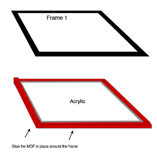
Then I cut my frame out of MDF because the aluminum L type bar I had was much to hard for me to work with considering the tools and skills I had. I cut out 2 layers on on top of the other then put in my acrylic and cut strips of MDF and glued them around the boarder to create a frame that it would sit in. Which the other layer would sit on top of sealing it in. This might not make sense so heres a diagram.

Once you've manage to wire up all your LEDS according to the diagram its time to test it all works. I should note first those when wiring and soldiering in the parts together take your time and wire everything correctly and double check everything as you go. If your camera has a nightmode like mine feel free to turn it on and enjoy seeing your LED work. Then take one moment to realise your project is actually working (so far). If they don't work double check your power source and ensure your LEDs are wired the correct way etc.


I used a small RCA connector to allow me to unplug the power from my frame in case I need to do repairs or take it apart for anyreason.


Completed frame covered in black duct tape with USB power cable.

Wednesday, September 24, 2008

The Build so far

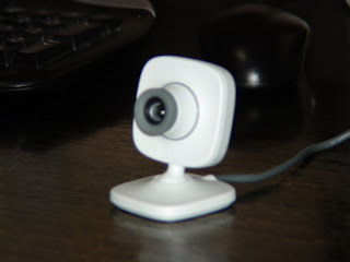
Ok so first off I started with modifying the Xbox Vision 360 camera by removing the IR filter.

I followed a simple pdf guide from put together by the good people of nui group you can find a link here. This was a fairly stright forward process with little difficulties.

Then I took apart my 17" hyundai monitar.
Taking the monitar apart just involed snapping all the plastic off with a flat head screw driver, and then removing a few screws.

Pop it out of the plastic housing and then turn over.


Undo all of the screws at the back holding on the metal, which is hiding the circuit boards.


Take off side rails by simply unscrewing them.


From here you can disconnect the circuit board wires on the back and go around the frame and unclip all of the edges and pull the frame from the panel and layers of diffusers


From here you should work out which layers your going to keep behind your lcd and which your going to get rid of. This is the one thing I couldn't find much information on which layers to keep or discard so I got rid of the last to but kept the big plastic board part and the layers underneath. Then I check with a remote control if IR light would be picked up through my modified camera. It worked so I'm gunna use these and I'll see how these work out.

Its now probably a good idea to double check your monitor is still working after all that tinkering. So I layed it all out on a table and plug in all the circuit boards to check it out.


Once you know its still working its time to continue with the rest of the build.

Sunday, September 21, 2008

Parts Collected

Ok so yesterday I was able to gather all the parts together that I'd need to complete my FTIR LCD multitouch setup.

Heres what I was able to get:

Dicksmith: 15 IR LEDS and some resistors
Bunnings: Acrylic, screws, bolts, some aluminum L shaped metal and MDF for my box that will contain everything.
ebgames: Xbox vision camera


I was able to get all the MDF I wanted for free. Bunnings has a lot of spare MDF that they get as lids for shipments or something so if you ask politely they will give it to you. Other wise they just throw it out.


(free MDF)

I already had a 17" LCD and various other materials available.

So now all the purchasing is complete I'll be trying to give you an in depth construction process from all the information I've learned from various blogs and of course the great www.nuigroup.com

Wednesday, September 17, 2008

Parts, materials and design

Ok so after much debate with myself thinking and planning for the design of my FTIR LCD setup I have come to a conclusion. Due to quite intense time constraints on my project I will constructing a simple cube. Roughly: Height 42cm, Width 45cm and 65cm Depth.
I really hate that I'm basically throwing out any ability to design something nice but unfortunately its function over form at the moment.

The Parts:
acrylic
IR Leds to surround frame
Wood for Box (MDF)
Webcam (with ir filter removed)
17" LCD mounted inside box with accessible cables.
Power supply for IR LEDS
Compliant surface (silicon pour onto acrylic)

I'll be purchasing all the parts soon and will start construction soon.

Thursday, September 11, 2008

Blog created, now for some content

Ok step 1 is now complete I have a place to put information about my upcoming project. During the coming weeks I'll be attempting to design and build a multi-touch screen.

I'll be using an old LCD monitor, perspex, IR Leds and a web cam to create a FTIR multi-touch interface.

So please come back later for more information about design construction and applications.